What is an Arduino?
Arduino is an open-source electronics platform based on easy-to-use hardware and software. It consists of a programmable circuit board, or microcontroller board, and a software development environment that allows users to write and upload code to the board.
The microcontroller on an Arduino board is usually an Atmel AVR or ARM processor, but other microcontrollers can also be used. The board also includes input/output (I/O) pins that can be used to connect the board to various sensors, actuators, and other electronic components.
The Arduino software development environment is based on the Processing programming language and provides a simplified interface for writing and uploading code to the board. This makes it easy for people with little or no programming experience to get started with building electronic projects.
Arduino is widely used by hobbyists, artists, and designers to create interactive projects such as robots, electronic art installations, smart home devices, and more. It is also used in educational settings to teach programming and electronics to students.
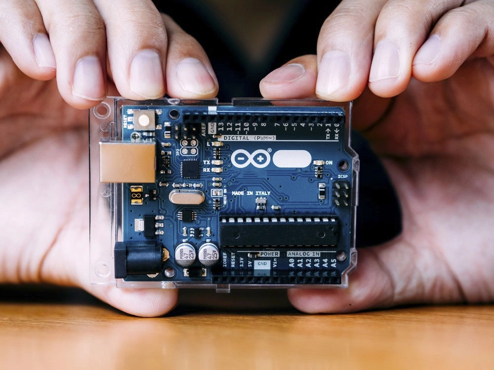
The Arduino Uno is a popular board within the Arduino family and is highly recommended for beginners. We will talk about what is on it and what it can do later in the tutorial.
What is on the Board?
The Arduino board typically contains the following components:
In addition to these basic components, some Arduino boards may also include additional features such as built-in Wi-Fi or Bluetooth connectivity, SD card slots, or built-in sensors.
Power (USB / Barrel Jack)
Arduino boards can be powered in two main ways: through the USB port or through the barrel jack.
Pins (5V, 3.3V, GND, Analog, Digital, PWM, AREF)
Arduino boards have several types of pins that can be used to connect to and control external components. Here are some of the most common types of pins:
Reset Button
The reset button on an Arduino board is a small push button that is usually located near USB Jack of the board. When the button is pressed, it resets the microcontroller and restarts the program from the beginning.
Power LED Indicator
The Power LED Indicator on an Arduino board is a small light that provides visual feedback about the power status of the board. When the board is powered on, the Power LED will typically light up, indicating that the board is receiving power.
If the Power LED is off or not lit up, it may indicate that the board is not receiving power or there is an issue with the power supply. In such cases, you should double-check the power connections, ensure that the power source is functioning correctly, and verify that the voltage provided meets the requirements of the board.
TX RX LEDs
The TX (Transmit) and RX (Receive) LEDs on an Arduino board are indicator lights that provide visual feedback about data transmission and reception through the boards serial communication interface.
Main IC
The main IC (Integrated Circuit) on an Arduino board is the microcontroller chip that acts as the brain of the board. It is responsible for executing the code uploaded to the board and controlling its various functionalities.
The specific main IC used in Arduino boards can vary depending on the board model and revision. However, one of the most commonly used microcontrollers in Arduino boards is the Atmel AVR ATmega328P. This microcontroller features a low-power, high-performance 8-bit architecture and is widely utilized for its ease of use and compatibility with the Arduino software.
Voltage Regulator
In the context of Arduino boards, a voltage regulator is an integral part of the board power supply system. It helps provide a stable and regulated voltage to the various components and circuits on the board, including the main microcontroller, sensors, actuators, and other integrated circuits.
The voltage regulator on an Arduino board typically accepts a higher input voltage, such as 7-12V from a power source or the USB port. It then regulates and steps down this input voltage to a lower, consistent voltage level required by the board components. For example, on the Arduino Uno board, the voltage regulator converts the input voltage to a stable 5V.
The Arduino Family
Arduino boards are typically characterized by their simplicity, user-friendliness, and open-source nature. They are designed to provide an accessible platform for individuals, including beginners, hobbyists, students, and professionals, to learn, experiment, and build interactive electronic projects. Here are a few options that are well-suited to someone new to the world of Arduino:
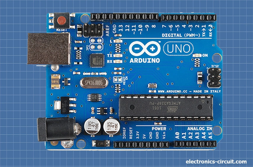
Arduino Uno (R3)
The Uno is a great choice for your first Arduino. It is got everything you need to get started. It based on the Atmel AVR ATmega328P microcontroller, a powerful 8-bit microcontroller that runs at 16MHz. It offers 32KB of flash memory for storing code, 2KB of SRAM for data storage, and 1KB of EEPROM for non-volatile storage. It provides a total of 14 digital input/output (I/O) pins, among which 6 can be used for pulse width modulation (PWM) output. Additionally, it has 6 analog input pins, a Power Jack, a USB connection, ICSP Header, Reset Button and more.
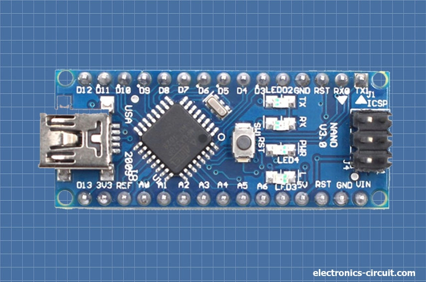
Arduino Nano
The Arduino Nano is a small and versatile development board that is part of the Arduino family. It has many similarities with the Arduino Uno as we discussed above but Its comes in a smaller Size.
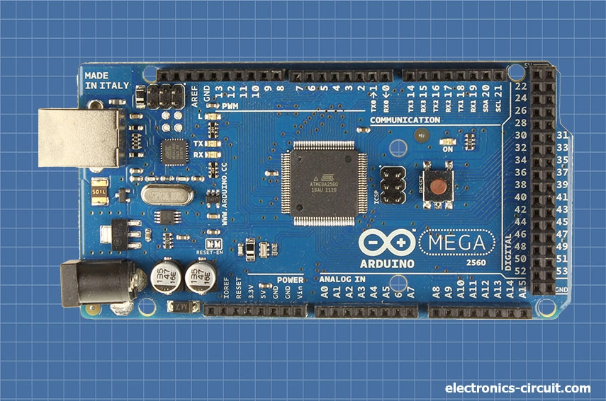
Arduino Mega (R3)
The Arduino Mega (R3) is a powerful development board in the Arduino family, offering an expanded set of features and capabilities compared to other Arduino boards. Its designed for those projects in which required a large number of input and output pins, higher memory capacity, and increased computational power.
The Arduino Mega (R3) is based on the ATmega2560 microcontroller, which provides 256KB of flash memory for program storage, 8KB of SRAM for data storage, and 4KB of EEPROM. It runs at a clock speed of 16MHz.
One of the main advantages of the Arduino Mega (R3) is its extensive set of I/O pins. It offers a total of 54 digital input/output (I/O) pins, among which 15 can be used for pulse width modulation (PWM) output. Additionally, it includes 16 analog input pins, providing a wide range of connectivity options for sensors, actuators, and other external devices. It has multiple communication interfaces, including UART, SPI, and I2C, allowing seamless integration with various devices and modules. The board also includes additional hardware features such as a USB connection, power jack, ICSP header, and a reset button.
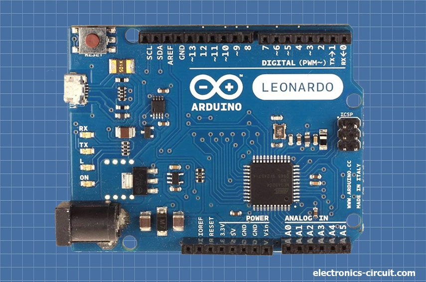
Arduino Leonardo
The Arduino Leonardo is a versatile development board, known for its built-in USB communication capabilities and unique features. It is based on the ATmega32U4 microcontroller. The Arduino Leonardo offers 20 digital input/output (I/O) pins, of which 7 can be used for pulse width modulation (PWM) output. It also includes 12 analog input pins and various communication interfaces such as UART, SPI, and I2C. These features provide flexibility in connecting sensors, actuators, displays, and other components to the board. One of the best features of the Arduino Leonardo is its ability to emulate a keyboard or mouse. This means you can program it to send keystrokes or mouse movements to a computer, making it suitable for projects involving human-computer interaction, input automation, or control of external devices.
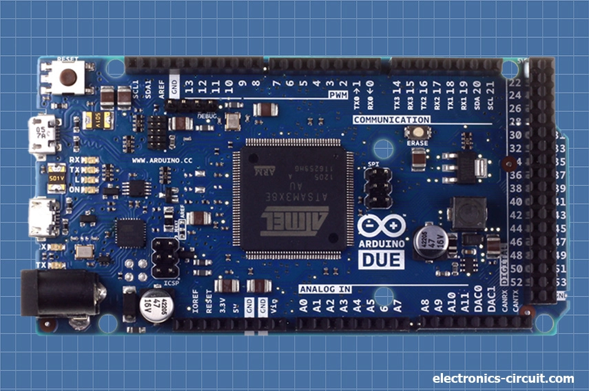
Arduino Due
Arduino Due is a powerful development board in the Arduino family, offering enhanced capabilities and improved performance compared to other Arduino boards. It is designed for projects that require more computational power, higher-speed communication, and advanced functionalities.
The Arduino Due is based on the Atmel SAM3x8E microcontroller, which features a 32-bit ARM Cortex-M3 core running at 84 MHz. It has more computational power and performance compared to the 8-bit microcontrollers found in other Arduino boards. Arduino Due offers 54 digital input/output (I/O) pins, among which 12 can be used for pulse width modulation (PWM) output. It also includes 12 analog input pins and a range of communication interfaces, including UART, SPI, I2C, CAN, and USB. These features provide extensive connectivity options for connecting sensors, actuators, displays, and other peripherals. Due has 512KB of flash memory for program storage and 96KB of SRAM for data storage.